|
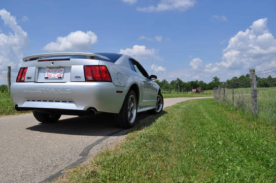
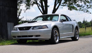
Project Silver Streak
The Car: Last
year (05-2010) we found a great looking, low mileage 2003 Ford Mustang GT in Washington D.C.. Yes, it was
a bit far to go for a car, but the thing was perfect and we couldn't resist. Koon's Ford had just
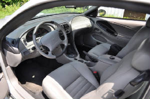
sold a new vehicle to a woman in which she traded in her Mustang on the deal. The car was loaded with every
option and had only been female driven. The Interior was spotless, as there had only been a passenger there a few times.
The car looked great, with one small flaw, a small scratch on the right rear fender well. You just
cannot find cars in this condition with regular factory service, and reasonable price to boot! So,
after a short look over, it was purchased and on the road home. What was the Price….$4700.00….161,000
Miles.
  Make:
Ford, Mustang Model:
GT Color:
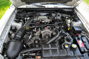
Silver Metallic Engine:
Ford V8 Modular 4.6L-2Valve Transmission:
Ford 4R70W Automatic Axle:
8.8 Ford, 3.27:1, Trac-Loc
Once home, we went over the car even further. Fortunately, there were no surprises to be found. It was
an extremely clean and well taken care of Ford Mustang. The only thing we could find wrong with it
was a very small leak at the thermostat housing. This allowed coolant to run into the front ignition coils and down the
valley of the block, exiting back towards the transmission. We installed a new Intake manifold, thermostat
and gasket to seal the leak, then installed new Accel Super Coil Ignition Coils to replace the factory units.
With the leak fixed and a healthy running car, we installed a Cat-Back exhaust system from MagnaFlow. The
system went on perfectly and the car sounds much better, with zero drone. Changed all fluids along with a deep
transmission pan. This was the extent of the modifications to the car till March of 2011, when we stated the project.
 ProWeld is using this car
as test bed for information on how different parts interact with each other and the car. The goal is
to go faster with each and every up-grade, but we wanted to take a different approach than most. See most
simply jump right in and throw a bunch of parts at a vehicle, with the goal of faster lap times. Well
that’s or goal too! Instead of the wholesale approach, we decided to go one part at a time route. Test it, tune it,
and track the changes. Were the results as expect or did they have a negitive impact. What was the car like on the track
and how was it on the street? Why you ask? Well why not? I don't
know of anyone else that has done anything similar and documented it, so I feel the challenge is a worthy one.
Plus, with the owner of the company being a Mechanical Engineer, it fits his inquisitive and orderly way of thinking.
It will identify the parts and pieces that work together and those that don't, and hopefully help take the guess
work out of the equation for those that follow. The car will eventually be turbocharged and run well into
the 9's, hopefully 8's, while still being streetable. We have plenty of engines and transmissions
that will accomplish our goal. The real challenge will be to match the engine's performance with a supporting chassis
and safety gear.
"Always plan for it to cost twice as much money and take 4x longer
than originally planned" Stage 1: Parts Corbeau FX1 Pro Racing
Seats, Qty. 2. Adjustable Seat Tracks, Qty. 2.
Rear Seat Delete Kit
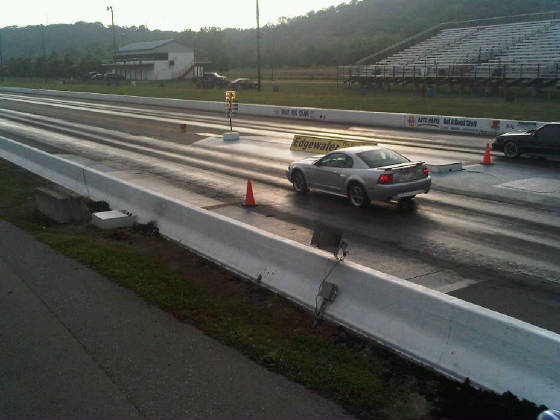
Stage 1 was a simple assessment of the car's performance. Many 1/4 mile runs were made, noting
Air Temperature, Humidity, Barometric Pressure, Tire Pressure and so on. This gave us a great base to
compare future data to. We also got to experiment with different driving techniques to see what the car
liked and note what it's weaknesses were. Since our goal was a very quick streetable car. Front seats
were replaced with Corbeau FX1's and we removed the rear seat along with bracing and mounts, rear seat belts,
trunk liners, spare tire, and jack.
Stage
2 Parts Ford Racing 4.11 RP Gears W/Install Kit Moser
31 Spline Axels W/ARP Extended Wheel Studs Detroit Locker Rear Differential Axle
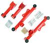
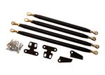
Seals & Bearings Axle Stiffing Brace & Welded Axle Tubes Upper
& Lower Control Arms & Poly Bushings Control Arm Mount Brace Kit Welded in Stiffler's
Weld in Frame Ties, Transmission Mount & Drive Shaft Loop
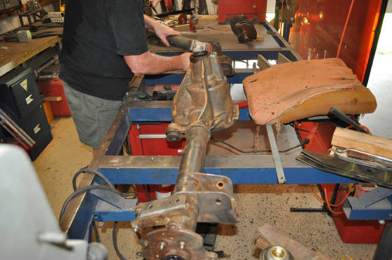
This stage was the first real hard core parts swap. We began by removing the rear end, control arms, brakes, springs,
and anything else that held the rear suspension to the car. Other than a few rusted bolts and a stripped
rear wheel sensor, everything went pretty smoothly. We brought the rear end home to clean, strip and re-build.
The rest was left in the garage.
 The
rear end was stripped back at home, we removed the bad bolt and ABS sensor, the ring and pinion, the axles and outer adapter
plates. First up was a complete sand blasting, which removed 80% of the dirt, grease and grime.
Next I took a side grinder and ground down the trouble spots, and where we would be welding. A switch
to sanding disc and it housing started looking much better, from there I switched back and forth from wire wheel to sanding
disc, until the housing was spotless and smooth. Sounds easy enough, but it took the better part of a day
to complete. The idea here was to get the housing smooth and clean so we could paint it, for a nice look.
Next came the housing welding, the axle tubes needed to be welded completely around the area they were pressed into
the housing. Ford only takes the time to spot weld the tubes in place, which under normal circumstances
is OK, but when drag slicks are involved, don't quite hold up. So we welded the axle tubes completely,
then installed the tabs for the rear axle tube brace. A set of supports that attach to the housing and
the other end to the tubes, forming a brace to prevent flexing. With that done, it was off for another
sand blasting, more touch-up and then a complete clean and rinse cycle. We had to make sure the sand was
completely out of the housing, which takes time, since it gets into everything and everywhere.
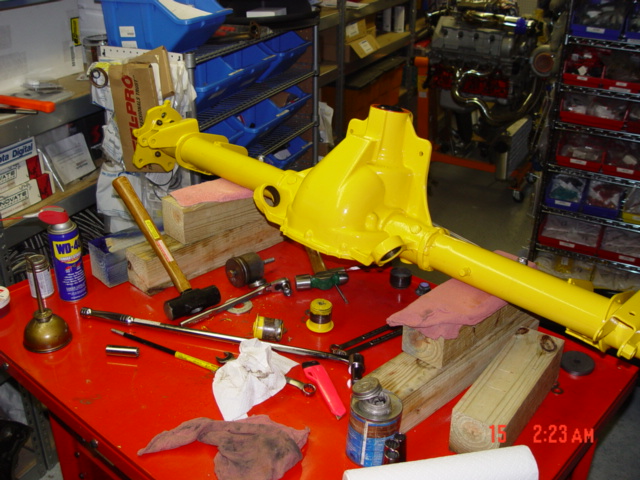
Once clean and dry, the painting process began. First a bare metal primer, followed by 3 coats of
Yellow, and then 3 more coats of clear. We painted the axle housing itself, the two adapter plates on the
ends and the pinion flange. Why YELLOW? Because
I like it. And it looks sharp with the silver braces and aluminum cover plate.
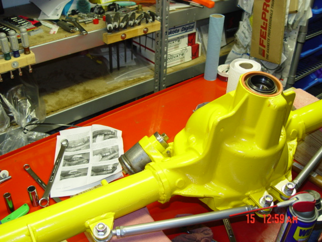
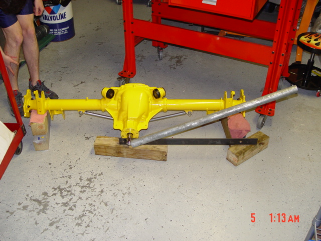
Figure
1 8.8" Ford Housing just painted and ready for the seals and bearings. Note
upper bushings are removed.
Rebuilding the axle housing was next, we removed the old seals and bearings from the axle tubes and pinion snout.
Installed new bearings and seals in the tubes and all the required parts for the pinion assembly. The
axle braces where installed, and looked great!
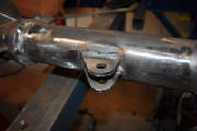
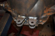
 Figure
2 8.8" Ford housing pressing out upper bushings using the maximum Motorsports Tool.
Pinion Seal is installed along with lower support braces.
Next it was time to re-bush the axle housing itself….The old OEM Ford rubber axle bushings were worn and just
not up to the task. We purchased new polyurethane bushings, which are much firmer and control the
real axle assembly better. Only problem was we now had to remove the old bushings, which are a chore.
We started by removing the bushings and their housing from the rear end, these are pressed tightly into the horns of
the axle, and are very hard to remove. We used a special tool made by Maxim Motorsports. You
do not have to remove the housing to replace the bushings, but since our axle was out of the car, it seemed easier to do so.
Once out, we pressed the center bushing out of the rubber, and tried our best to press the rubber out as well.
Of course it will not press out, but we managed to get some out. The rest we
had to cut out, drill out and then take a very small wire wheel and grind out till we had nothing but the housing left.
Now, you can lube up the new bushings and press them in, then lube up the center metal bushing and press it in as well.
The outer bushing section will simply slide on the other side, once installed back into the axle horn.
Again, we had to use the special tool we purchased to force the new bushings and the housing back into the axle horn.
This is not easy, and requires some force, so be prepared to use some muscle. I would recommend
that before you start with the rear end bushings, take the time to make a few critical measurements. Measure
the outside to outside distance between both upper bushings, this way you will know how far to press them back in.
Good advice since they have to fit back inside the upper control arms, and you don't want to get caught short.
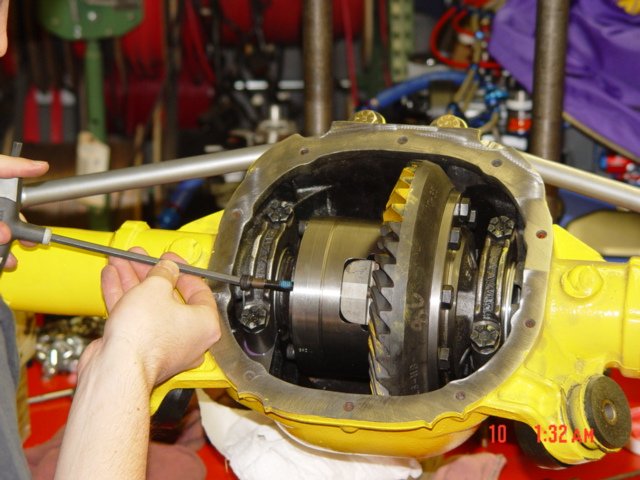
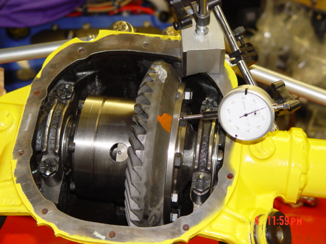 Figure
3 Checking run-out on the carrier assembly.
We pressed the new differential side bearing on, as well as the pinion bearings. Installed the ring
gear to the new Detroit Locker, and locked the bolts in place (red lock-Tite). First we insured the ring
gear and carrier was within spec for run out, it should be 0.003" or less on the carrier, 0.004" or less with ring
gear installs, ours was around 0.0015" to 0.002". For initial set-up, we used a stock Ford spacer
and a combination of kit spacers on the pinion side, we will get a better idea of what is needed later on. Once
finished, we removed the parts, and made way for the pinion assembly. The bearing rest had already been
replaced, they are the actual bearing surfaces the new bearing will ride on. With that done, we assembled
the pinion shaft, with a crush washer installed and slid it up and into position, while another positioned the drive flange
over the spines and secured the nut. Here you have to draw down the pinion nut, by hand, no air tools,
and crush the sleeve till you have between 20-30 lb-In of drag on the bearing. It is measured by turning
the pinion nut with a Inch pound torque wrench. The trick is that is requires
a lot of torque to tighten the self locking nut, and then more torque to start the crush of the sleeve, around 250 lb-Ft!
The difference between a 20 LB-IN drag and a 45 LB-IN Drag on the pinion bearing is about 1/10th turn.
So, once the slack is taken up in the pinion shaft, slow down and take your time tightening the nut. It
took us three attempts to get it right, the first time we went 55 LB-IN and second, 40LB-IN, the third was right on at 25
LB-IN. Buy extra crush sleeves when you purchase your parts, you will need to develop a feel, a feel that
takes time and sleeves to get right.
 Figure
4 Here we are tightening the Pinion Flange Nut, to preload the pinion bearing.
This is none by crushing the "Crush Sleeve" with the pinion nut till you acheive 20 to 30 LB-IN of
drag on the bearing.
With the pinion now set, it time to re-install the pinion and carrier with the factory width spacers for the first
trial fitting. We need to measure the back-lash of the gears, that's the amount of free space between
the gear teeth themselves. The factory specs call for 0.008" to 0.014", our fist measurement
was 0.016", so we knew we needed to bring the ring gear closer to the pinion gear. To do this, we
had to change the pinion bearing spacers, out went the factory spacers, and in came a set of adjustable units that came with
the install kit. We ended up with a ring gear thickness of 0.244" and a pinion thickness of 0.260".
This combination gave us a 0.010" back lash adjustment, right on the tight side of the specs. When
the final assembly takes place, we will need to increase both side spacer thickness by about 0.006", this is how you
get the pre-load on the bearings. Also, when installing the side bearing plates, take the time to pull
them down evenly and once snug, do the Chris-Cross pattern evenly till about 30 Lb-FT. On the final tightening,
I will apply Lock-Tite and torque to the 75 LB-FT spec. Time to check that pinion drag again and the actual wear pattern on
the ring gear. The first is easy and quick, use you inch pound torque wrench to turn the pinion nut and
make sure it isn't out of spec. Now apply the supplied grease, yellow in our case, and spin the pinion
both forward and backward several times, to establish the wear pattern in the grease. Now, look carefully
for any patterns, are there more marks on one side then the other of the teeth? Does the marks seem centered
and even in wear? Check both front and back sides of the gears, that represents the drive and coast sides
wear pattern. We had a great pattern, well centered and very even. Take your time and
spin the assembly many times, both forward and in reverse. it takes some time to transfer the grease pattern,
and you won't a clear picture of what that pattern is.
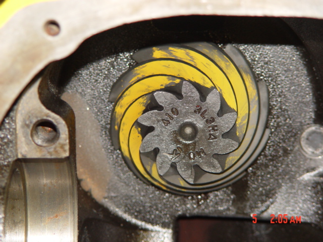
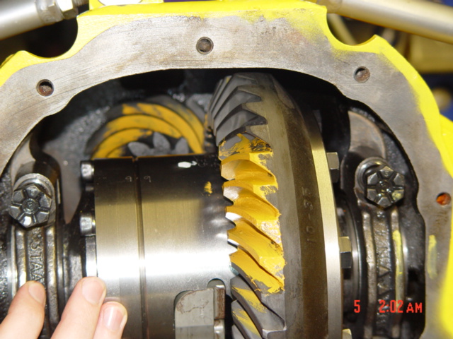 Figure
5 Checking the wear pattern on the Ring & Pinion Gears
Figure
6 Another look at the Pinion Gears
With the Pinion set and a good wear pattern, we simply had to do a final assembly and button this guy up.
Fist we removed the bearing side caps and separated the parts by side and in order. Then we removed
the differential and set it aside.
 Now
I needed to clean the gasket surface area of the rear cover. I should have done this many steps before,
but sometimes that's how things go! Anyway, with all the internals removed and the open area covered
up, I used a 3M 3" scotch bite pad to clean the area around the cover sealing surface, this took all of 2 minutes and
made little mess. Now with everything clean again, we started the final assembly. We
needed to preload the side bearings, so first we measured what we had (Thickness of the spacers), and added to that amount,
the same on each side, in our case some 0.004". This is harder than it sounds, you have a limited
amount of spacers and a specific thickness target to accomplish. Once the spacers were the right thickness,
we re-installed the differential and spacers, then bolted in the support caps. Because you are pre-loading
the side bearings, you will have to help the last spacer you install, into place. be careful and take your
time, we simply had to tap it with the wood side of a hammer handle. Once everything is in place, install
the side caps and X-cross the bolts till hand tight, then do the same in steps of 15 - 30 - 50 - 75 LB-FT. I
also used some red Lock-Tite of the bolt threads. All most there!
 Figure
8 The Axle is about finished. This is the socket head cap screw that holds
the axle bar in place. Here we are installing the screw, as the axles and C-clips are already installed. The Rear-End is about finished, at least the hard part is done. Now we get the axle locking
plate out of the differential. it is the plate/bar that is held in place by the socket head screw that
is not locked down and hanging out. Remove that one screw, and the bar will come out. With
the bar removed, we can now slide in the two axle shafts, ours are 31-spline, but whatever you decide to go with, make sure
they match the differential! Slide in each axle, I like to apply a little oil on the axle seal beforehand.
They should slid in, then have to be slightly lifted on the diff side to engage in the gears, so lift and turn.
Push all the way in, and now go to the diff and install the C-clip, on the end of the axle itself. This
is a small C-shaped clip that prevents the axle from sliding back out. Once the C-clip is install, go back
and pull the axle out as far as it will go, this will allow the bar to go back in. Repeat for the other
side and then re-install the diff bar, using the socket head screw you removed. Ok, the axles are in and
you pretty much finished. The wheel studs should have been already installed before the axles were, hopefully
this was the case with you. Now, let's apply a liberal amount of RTV sealant around the cover and axle
housing. You should go around every cover hole and don’t worry about the stuff that will seep out,
we will take care of that latter. I like to wait till the RTV is tacky, then install the cover plate.
We are using a Aluminum center support cover, so after the install of all the cover plate screws, we will pre-load
the main support caps to 20LB-FT, then lock now the lock nuts. Do not fill the axle with rear gear oil
for 24 hours. And once you are ready to fill the axle, you can also trim off any RTV that was pushed out
for a clean look.
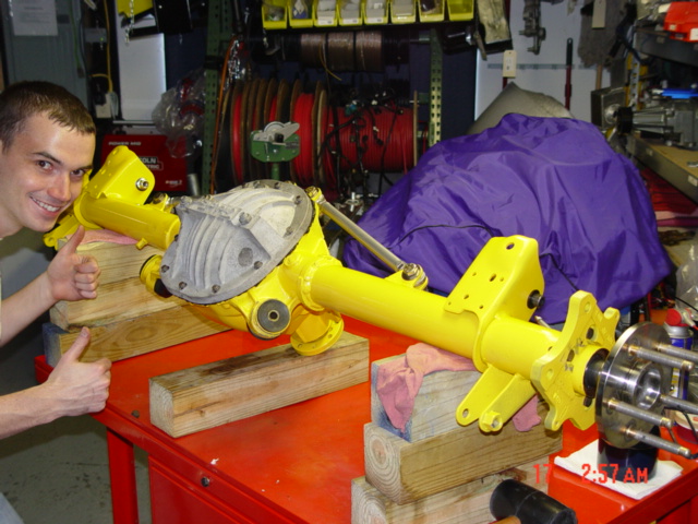 Figure 9 OK,
the axle is done! We will fill the axle and trim the RTV from the cover after 24 Hours. Next
up...It's time to install back in Project Silver Streak. Installing
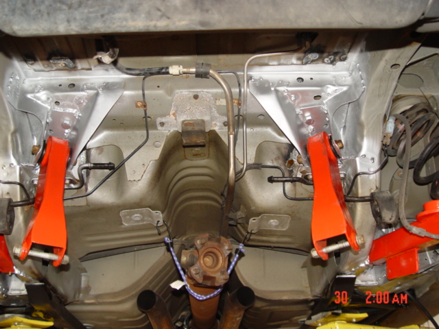
the Torque Box Plates
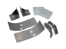
The Torque Box strengthening plates in the kit were first to be installed. Yes
they say it's a simple bolt-on deal, but it's much more then that especially it you want to get the most out of your
money and effort. The plates that fit up and into the control arm sockets were made well and fit pretty
good. You simply had to drill a few holes and install the bolts they provided. The outer
braces were much different, the lower control arm brace require that you cut some of the metal from the lower mounts to install
them, while the upper outer mounts were not even close to the right shape. These are the larger, half round
pieces that fit inside the rear deck of the car. While I suppose one could bolt these pieces in and be
done with it, I doubt very much if you really would gain any strength. Especially since you removed strength
just to install them. We welded all the brace in place, which made for a much harder job, but also for
a much stronger install, one that will strengthen the chassis and it's suspension mounts. The longest
and most time consuming part is removing the undercoating or sound deadening material they install at the Ford factory.
This stuff is a thick tare like substance that has to come off before the plates go on. It is useless
to try to weld to anything that has the slightest amount of tare on it, so do your job here and get all of it off.
We tried dry ice at first, the ideal being that the extreme cold would harden the tare and allow it to break off.
This worked Ok on the flat areas, like in the foot wells, but not so well on the other areas. For
those spots we resulted to the side grinder with a sanding disc. It got the stuff off, but also made a
huge mess of the surrounding areas. Really, there is no easy, clean way to do this…so be prepared
for a long day of working on knees bent over the back area of the car. We had the seats removed and carpet
out, I cannot see how you would do it any other way. Once the area is clean and ready, we installed the
plates and welded them in place. Like I stated before the upper reinforcement plates were nowhere close
to the shape we needed, so we had to form them ourselves, and press them down with a jack for welding. We
welded the angled fitting on the upper plates for extra strength as well. The original unibody material
is very thin, and welding the plates in, takes a lot of patience and time. In my opinion the braces would
be better left off, it you did not intend to weld them in place, I think they would weaken the structure more then re-enforce
it.
  Personally, I feel welding
in your braces is the only way to go. You will receive some benefit from a bolt in application but welding will
yeild you the most strength. We also welded the OEM mounts around their perimeter for more strength, as they are
originally only spot welded in a very few places, this probably gained us the most strength, over all other things.
Rear Control
Arms
When
you install the new control arms, do not forget to take the time now to lubricate them. Silicone grease
is the preferred lubricant, as it will say with the bushings for the longest time and provide the best service.
You should not only lubricate the side surfaces or the bushings, but go ahead and use the grease gun loaded with silicone
grease to load the poly bushings with a healthy dose of grease. It is much easier to do this on the bench,
then rather up in the air with the fitting being restricted. We'll leave the rear most section alone
for now, as we don't have the rear end ready to go back in, and we have other items that need to be installed first also.
On the install….Once were to the point of installing the rear axle back in the car, we found a few minor problems
with the rear control arms. First, the bolts they provided for the lower control arms to axle mount, were
not right. They were way too short. What we needed was M14 x 110mm, not the 1/2'
x 4" bolts provided. Also, the upper control arms to rear axle were not the right size or length.
We needed a smaller M14 bolt not a 1/2" one to fit the smaller size bushings, plus they have to be the longer
length of 110 mm. With the right size bolts, the rear end goes back in very easy. We
used a transmission jack to support the axle, then worked it through both rear brake cables, and up into place.
We used poly spacers for the rear spring, and with those in place simply placed the rear springs up into their place,
and the big end on the control arms, and jacked the axle up and into place. We did have to strap the car
down to the lift, the transmission jack wanted to lift the car off the 2-post jack's arms. so with
that done, we installed the top control arms, then the bottom ones, and tightened all the control arms bolts.
Then we installed the disc brake backing plates, caliper mounts, and calipers, along with disc brake. Next
came the sway bar which bolted with two bolts to each lower control arm, and the driveshaft was bolted up to the Pinion flange
with four bolts. Now, we re-installed the exhaust system and re-aligned the chrome exhaust tips.
The shocks were installed, along with the lower shock mounting clips, one on each side of the rear axle.
Do yourself a favor and apply some grease to the rubber exhaust mounts, so next time you take them off, it won't
be so pain full. Now, it's just a few clips to hold the brake cables in place, and a good look over
to make sure everything is in and tight.
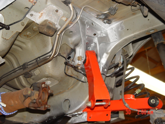
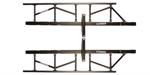    Installing
the Subframe Connectors I really like the Stiffler's products.
I first saw them at the 2010 NMRA national event in Bowling Green, KY. They are well made and really
supply a lot of stiffness. We started the installing both lower Sub fame connector bars. These
were very simple to install, you first remove the rear two front seat bolts and replace them with supplied longer bolts.
Then attach the Subframe connectors at the cross mounts where the seat bolts protrude, with supplies nuts.
This will hold the connectors in place for you while you square them up and mark the areas that will need sanded prior
to the welding. It's much easier to simply remove all the tape they applied to the welding surfaces
at one time, and be done with it. Having marked the chassis at the spots that will be welded, you have
to remove the connectors and grind or sand the area to remove paint and any other contaminant, then re-install the connectors
and tack in place.
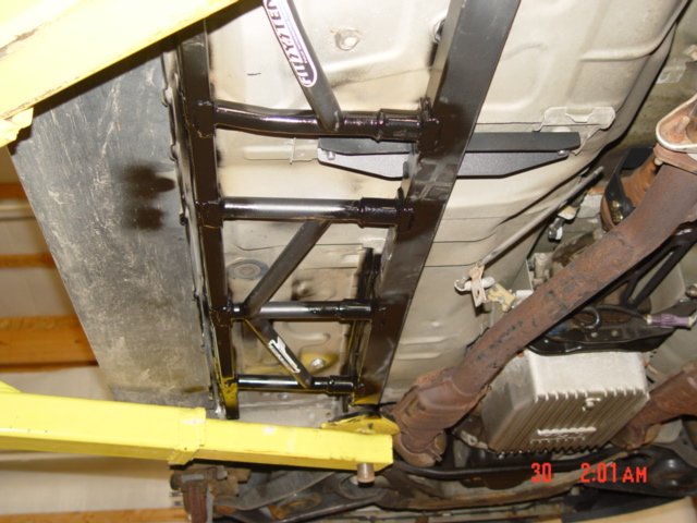
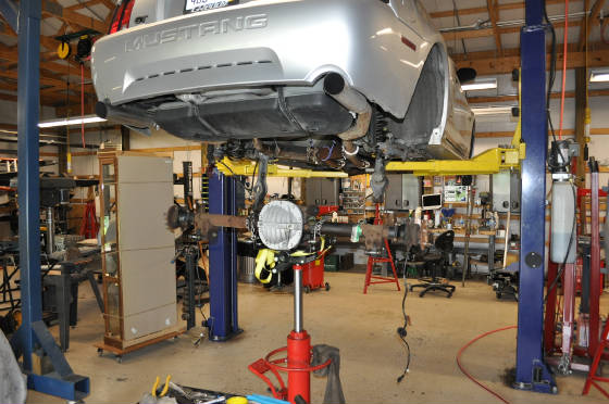
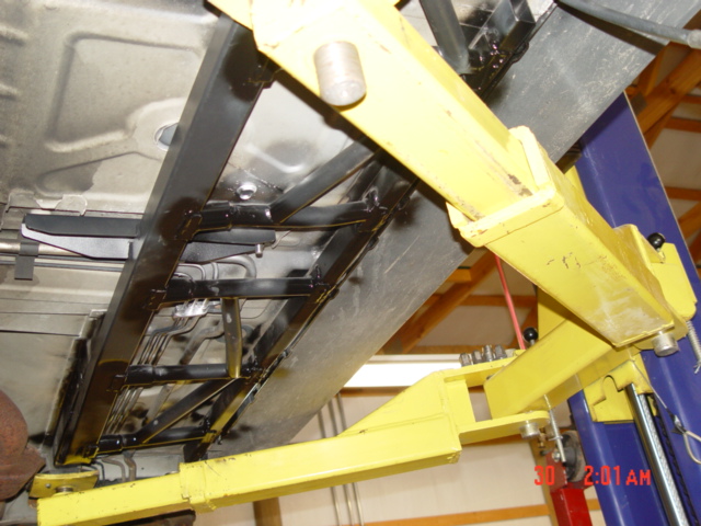
We left the two main connectors tack welded and then went on to the installation of the driver's side complete
system. The connectors have to go on fist since the rest is based off the connectors. Personally
I don't know how you would do this job without a lift, I know there are some out there that might attempt it, but it would
be very difficult. We used under car jack stands to hold the cross pieces and the outer brace in place
while we fit them up and marked the weld areas. then removed them and sanded the areas as we did for the
connectors and reinstalled everything, starting with the front section fist. Again we tack welded the outer
brace in place, then shimmed it down in the front till it was level and tack welded it in. The front cross
brace was installed, and tack welded in place also. Now the rear most cross brace was installed and tack
welded also, this completed the initial installation of the driver's side. Everything looked good,
so we decided to go ahead and complete the welding on that side. Note here, even though they gave some
surface area of un-painted area, take a sander disc and elaborate on that, and make sure there is ample metal to weld to.
this stuff they used seemed like epoxy power-coating, which will not weld! Also, clean the tubing
where it will meet the slip fittings, so you can weld that area without the worry of the epoxy getting into and contaminating
the weld. Once welded completely there was a very noticeable stiffness to the car. The
passenger side is exactly the same just and mirror opposite. One word of caution, is to watch the gas lines
and break lines that run up that side, one bad move there could easily start a fire or worse. Be careful
and use a spotter and some protection of the lines.
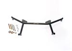
 Drive
Shaft Loop
The
Stiffler's Drive shaft Loop is very easy to install, simply remove the two rear transmission mounting bolts and add the
safety loop and new supplied hardware. literally a 15 minuet job and the loop works very well.
We will install the Center Triangulated Brace latter on, when we do the Front K-Member and Brakes. New
tires & Wheels
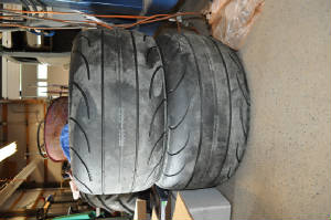 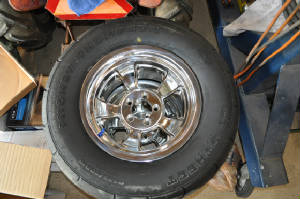 The
Wheels are Summit racing, Pulsar aluminum wheels. They are different looking, which I like and very, very
light weight. The front tires are Mickey Thompson, ET Street's. In the rear is the
same Summit Racing Pulsar wheels, in 15x10, with Hoosier Drag Radials. For Wheel studs we went with the
ARP 5/8" x 3" studs, you will have to drill out the axle flanges to install them, then press them in place.
Honestly, we used a old lug nut and impact wrench to pull them into place, just use some quality anti-seize on the
threads. I would have pressed them in place, but with our press, the studs would not align properly.
Self-centering studs are the only way to go, and one has to wonder why all wheel studs are not made that way?
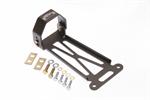
Stage
3 Parts Moroso Battery Relocation Box Nitrous
Oxide Kit
|