The Machine Shop Experience and Reality
Ok, we have removed the worn-out engine, sent it to us or you're going to do
the work yourself. We covered the striping process earlier, so you should be down to the bare block or very close to
it. This is where we start thinking about the machining process....typically. If you gave this some thought, you
would have been thinking about this step way before the engine was pulled. I'm going to use this chapter to bring
you up-to-speed on the machining process, the typical Machine Shop, and what is realistic and what is not.
I've found that with our over-abundant
use of electronics, internet, home computers, and in general, the digital age....we have gotten into a un-realistic expectation
of the typical Machine Shop, and the Equipment they should have on hand.
Most that attempt this type of engine re-build, are doing it for the first time,
and are not professional mechanics. They are not familiar with engine re-building and they most likely have never ventured
into a machine shop. But...They have no doubt seen pictures of expansive machine shops, and others doing this type work
on the web, in magazines and through other mediums. Yes, there are places out there, like NASCAR Engine Shops, Engine
Manufacturers, like Ford, Chevrolet and Dodge, and some larger
engine Re-Manufacturing Facilities that do have the latest and greatest in way of engine machining machines and equipment.
It is very impressive what the newest machines are capable of doing, in both speed and the ability to do the work basically
man free. These shops have tremendous funding, and can afford to buy the latest in technology.....But, do not expect
the local Machine Shop to follow this new found technology way. Why...In one word, MONEY! Those new machines are
extremely expensive, and way beyond the means on 98% of all Machine Shop owners. So, does this mean they cannot machine
your Ford Block right, or precisely? NO, it simply means that they will be doing the work on older machines. Machines
that are capable of doing the same processes the high dollars machines can do, but most likely much slower and with a machinist
standing by the machine while the work takes place. The biggest advantage the newer machines offer over the older ones
is digital control, the ability to place a block in the machine, look up that particular engine from a memory full of engines,
and have the machine do the work, with -out the machinist standing by while the work is performed. You can see the savings,
one machinist can now be free to do many jobs simultaneously, which allows the machine shop to cut its labor cost and speed-up
production. This is good for huge shops that re-build vast numbers of stock engines, and it's great for high dollar
facilities that have the money for the latest and greatest in way of equipment. BUT, this does not mean your local Machine
Shop, with its less than new equipment, cannot machine your Block, Head or whatever part you have, precisely, efficiently
and safely. It will take more time, but it will be just as good as one from any other machine....Provided, the machine
has been maintained and the machinist is skillful and diligent in his profession. AKA, knows his stuff and takes pride
in his work!
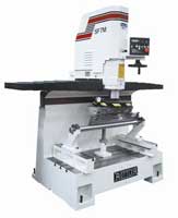
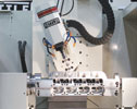
Today, the typical newest and greatest engine machining center, that would take a Block and bore its Cylinders automatically,
cost close to 1/4 Million Dollars! That is a huge amount of money and
a sum that would take a small machine shop a lifetime to recover. Think about it, at $30.00
a cylinder, you would have to do 8,333 cylinder to just break even. And that does not include overhead, labor or materials
cost! In real life terms, one machine financed over a 5 year period, with overhead, labor, and need materials to run
it, would turn into $1,760,000.00! Now, how many cylinders would you have to do
to break even...58,666! Now, can you see why your local machine shop may not have the newest piece of equipment?
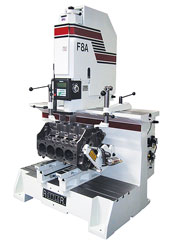
And please remember, that was just one necessary machine, you would still have to have a Surface Milling Machine, Crank Polishing
Machine, Engine Cleaning Machine, Engine Balancing Machine, Rod Machining Equipment, Piston Cutting Equipment, and on
and on. All costing extremely a lot and needing personnel and replacement materials to keep going.
So....What should you expect to find
at a typical local Machine Shop? First, you will find a very hard working staff, these guy spend all day inside a busy
shop, working on other peoples projects. Machinist, are the back-bone of our economy, and don't get the recognition
or respect they deserve. While 95% or America deals in terms of Miles, Yards, Feet and Inches...these guys live in a
world that is ruled by Thousands of an Inch or Mil-Meter. That's a lot of pressure, every day and all day.
I have yet to meet a stupid machinist, those types seem to get sorted out very fast in this industry. I am very fortunate
to have several very good Machine Shops in my area, and if you send your engine to me, that is where it will end up.
Depending on the service and type of engine to be built, I chose the right shop for the project. I would spend
as much attention finding a good Machine Shop, as you do pouring over all the shiny new parts you're going to install,
for without their service, done correctly, the rest really doesn't matter.
What should you look for and expect when looking for a Machine Shop? First
and foremost, the shop should be BUSSY. I have never seen my local guys not. Second, don't expect it to be
white glove clean. Efficient and well thought out, but not clean. The services they provide create a lot of dust,
dirt and oily haze. So, while it should not look like a garbage dump, it should be orderly, with assigned duty stations,
and broken into section for the desired service. As mentioned before, they will not have the shiny new machines, but
what they do have should be working, in good condition and complete...meaning nothing taped together or obviously rigged to
work. This is a tough environment, they deal in dirty greasy engines, and that other bring to them for service.
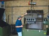
Generally, the engine is completely grimy, and they start by giving it a good cleaning in a Cleaning Machine, this will not
be the final cleaning, but enough to remove 90% of the grim, and make the engine easier to handle. I, do not deliver
anything to my Machine Shop dirty. I have way to much respect for them and myself, to do so. Once the parts are
cleaned, they will go through a series of test and measurements, to confirm the parts are serviceable and to register what
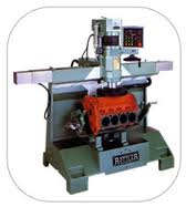
service is needed. When dealing with a Ford Modular Engine,
be it a 4.6L, 5.4L or the newer 5.0L engine, they all typically will need a Cylinder Bore & Final Hone to put the Cylinders
right. The Deck is often in need of a new surface, so they generally try to only remove just enough material to true
it up, generally just 4-8 thousands of an inch (0.008) will do. This is because the Ford Engine uses the MLS Head Gaskets, or Multi Layered Steel Head Gaskets. These allow
the Head to seal the top of the Cylinders and remain sealed, even with the Block and Heads expanding and contracting at different
rates. The MLS Gaskets require a very smooth surface, and in order to get that very smooth surface, we generally have
to re-machine the top of the Block and the under-side of the Head. Both surfaces should only be milled as little as
required, this process effects the compression ratio and other elements of the engine, like Piston the Valve clearances.
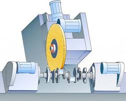
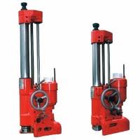
The
Main Bearing Journals, located in the very bottom of the Engine Block, will sometimes have to be machined, but always have
to be checked. This is done on a separate machine as well, a Line Boring Machine, where all the Main Bearing caps are
bolted in place and a cutter is run through them to re-alien them to be parallel with the engines Cylinders. Generally,
this would be all that is required for the Modular Engine, unless there was a serious problem or maybe some custom work for
a performance engine like clearanceing the Block for a longer Stoke Crankshaft. With the Engine Block taken care
of, it's time to look at the Crankshaft itself. The Bearing Surfaces, both Main Bearing and Rod Bearing, need to
be smooth, all the way across. I like to use my finger nail, and check for ridges or other imperfections. At the
least, I will have it polished. If you have a 6-Bolt Crankshaft, I recommend tossing them and starting over with
a Forged 8-Bolt unit. I don't use them and neither should you...mind you we are not rebuilding a stock engine, that
isn't what we do here, and probably not what you want either. Assuming the Crankshaft is salvageable, which would
have been determined after they checked it and magna-flexed it, we will have the Journals re-machined if needed. Only
after the Engine Block and Crankshaft have been checked and machined, are you free to even think about Pistons, Rings and
Bearings!!! Those running a large blower set-up, this is the time to have the Crank Snout cut for a Double Key-Way.
This will provide much more assurance against the Pulley breaking the single key-way or worse. And yes the pulley will also
have to be cut.
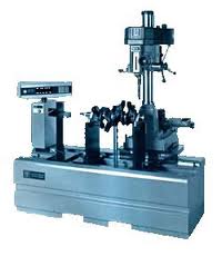
Balancing
Before we move on, there is one mandatory process
that is a most for any Performance Engine, and personally, I think it should be mandatory for ALL engines Stock or Race breed.
That process is called, Engine Balancing. This is the most important and meaningful single process you can do for ANY
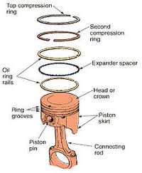
engine. To fully and properly Balance an engine, you first have to round up all the rotating assembly. That is
everything that spins and is attached to the Crankshaft. This would start with the newly re-build Crankshaft, followed
by the Pistons, which include the Pins, the Locks and the Rings you will be using. Next, you will need the Connecting
Rods & Bolts, the Flywheel or Flex plate and their Bolts, the Front Balance and any Pulley attached to it and their Bolts.
Use only the parts to be re-used in the actual build, meaning the real Bolts, Key Way to hold the Balancer, The Lower Timing
Sprocket and Timing Wheel can also be included in the mix. The key is to have everything that is attached to the Crankshaft
included, just as it will run. The more detailed you are, the better the overall Balance Job will be.
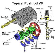
Crankshaft counterweights are designed to offset (or balance,
if you will) the inertia effect of a relatively heavy piston and connecting rod moving in both a rotational and reciprocating
(up-and-down) fashion at speed. The weight of the piston-and-rod combination affects the size and placement of the counterweight.
A longer stroke combined with a heavy piston, pin, and ring package requires a larger counterweight (more mass) to balance
the greater reciprocating weight. Most V-8 engines use large counterweights toward the front and rear of the crankshaft, leaving
the center portion without counterweights. That splits the engine into front and rear halves. The positions of the counterweights
on all V-8 90-degree crankshafts are the same. The height of the counterweight as measured outward from the crankshaft centerline
is limited by both the cylinder block and by the placement of the bottom of the cylinders. A counterweight placed farther
away from the crank centerline has more balance effect, but it is limited by the width of the block crankcase. Weights placed
toward both ends of the crank also have a greater effect and therefore don't need to be as large to effectively balance
the engine. This makes the overall crank lighter. If you have a 6-Bolt 4.6L crank, or a 5.4l crank, this is the type crank
you have…counter weights at each end. But if you have an 8-Bolt Crankshaft, you will notice a huge
difference, both in the number of counter weights, the placement of those Counter-weights and the overall weight of the Crankshaft
itself. The 8-Bolt Crank is a Fully Counter-weighted, forged unit. It has a counter-weight
at each throw, which make the unit much stronger, heavier and more accurate with overall balance. This
is why this is the Crankshaft for a performance engine! The strength comes from a more ridge, heavier unit
that also has 8-attachment bolts for the flywheel, and the design allows for more RPM and a smoother running engine.
Internal and External Balance….
Ford has generally been known
as a manufacturer that changes the design parameters on its engine many times. Many early Ford engines
have been made with an external balance, meaning the engine was assembled in a way that to be properly balanced, it required
a weighted flywheel. Most might recall the 28oz flywheel? This simply meant the flywheel
which was indexed to the crankshaft flange, was off balance by 28 oz.…and this of balance was needed to bring the engine
into a balanced state when assembled. Problem is Ford often changed this weight, depending on the engine
type and year. For the Ford modular Engine, we have an Internal Balance or neutral balance engine to worry
about. Meaning the parts them self-rely of the balance of the assembly and not some additional external
weight. This makes life much easier.
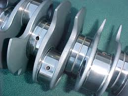
What is Engine Balancing? Look at your 4.6L Crankshaft, notice how the Crankshaft Counter-weights are really separated
to the front half and rear half? The Counter-weights are the huge rounded chunks of Steel on the opposite sides of the
Connecting Rod Journals. This basically separates the engine into a Front Section and Rear Section. The Counter-weight
is the huge piece of steel located on the back side of the journal throw. The Bob-weight, is the total
weight of the assembly that will attach to the throw. The factory engineers have figured this out and came
very close to the right counter weight needed, so a quick trip to the balance machine to fine tune the assembly is needed
for each assembly, and it’s ready to move on down the line. The problem for us is that the crankshaft
was balanced for the factory parts, and we are changing that assembly with different Rods (usually heavier), different Pistons
(usually lighter), and different Rings, Wrist Pins, Bearings and any other part changed to the front or back half of the crankshaft.
These subtle changes add up, and can throw the original balance off by quite a bit.
When mixing factory parts, you also have to remember, the factory has several different rods for the 4.6L engine, they
also have different Crankshafts, Balancers, Flywheels and Pistons, depending on what the engine was being used for.
All these different parts carry a different weight, so even staying with factory parts, the rotating assembly should
always be re-balanced prior to use.
The machinist will take your parts and use all those different weights
to determine what is needed to correct the balance. How this works is simple, you have
rotating weights and recipatating weight. Each Crankshaft Counter-weight is limited to the total Bob Weight,
But is close to what is expect to be run, for simplicity say your Bob Weight is 1600 grams. It would be very close to
the factory total counter weight, but because we are running different Pistons, Rings Locks, and HD Tool Steel Wrist Pins,
our Piston assemblies are way off. The problem gets worse when we up-grade to heavier, beefier Rods, like say an Oliver
or Carrillo with larger and stronger Cap Bolts. Each Bob Weight on the Crankshaft is there to count-act one Journal,
and since each Journal accepts 2-Piston Assemblies, you will have to combine the weights of both assemblies for the true Bob
Weight on that Journal. Now to figure out the Total forces, we have to further Sub-Divide the Weight into 2-groups,
Rotating Weight and Reciprocating Weight.
Reciprocating Weight: The
Total Weight of the Parts that go up and down in the Cylinders.
Rotating Weight:
The Total weight of the Parts that revolve around the Crankshaft.
Parts like the Connecting Rods contribute
to both forms of Weight, so the Rod Bearing Weight and Big End of the Connecting Rods Weight goes on the Rotating Weight totals,
while the Small End Weight of the Connecting Rods goes in the Reciprocating Total.
Engine Part Rotating
in Grams Reciprocating in Grams
| Rod Bearing | 65 | | |
Rod Big End | 528 | | |
Rod Small End | | 77 | |
Piston |
|
475 | | Rings |
|
110 | | 0Wrist Pin | | 41 | |
Oil |
|
3 | |
Totals | 593 | 706 | |
Total Rotating Weight | 593 x 2= 1186 | | | Total Reciprocating Weight | | 706/2=353 x2=706 |
The Total Bob Weight Figure
we need in this small demo is 1186 + 706=1892 grams. If our Crankshaft had a Bob Weight built-in of 1600 grams, then
we are light on every Bob by 292 grams. In this case the Crankshaft would have to be drilled and Heavy Metal installed
to counter act the differences. So there are no surprises, Heavy Metal is much heavier than the metal it displaces,
and cost about $100.00 an inch. While this was a very simple example, I hope it gives some insight as to how complex
and time consuming balancing an engine can be. To make matters even more complex, rotating and reciprocating parts, gain weight
as they are accelerated and de-accelerated, as the engine goes through the power band....This makes parts that are out of
balanced even more dangerous and destructive to the engine.
Cylinder Heads
Now it's time to take the Heads or Cylinder Heads in for a look over. Generally all
Heads will have to be torn apart and checked. You can save some time and money buy doing this yourself if you like,
it's not very hard and goes rather quickly. However...When taking apart any Head that will be re-using the original
hardware, you have to keep all the parts in order as they came off. Meaning the Retainers, Locks, Valves, Lifters, Rockers
and everything else that came off that Cylinder, has to go back on that Cylinder, just like it came off. If you mix
up the parts, the parts will wear at a very fast pace and fail. We always replace the Springs, Retainers, Locks, Seals,
and Generally the Camshafts themselves. But you might not, so be very careful how you remove the parts. Note”:
Always mark the Cam Bearing Journal Caps before removal. They need to be marked with respect to
place and direction. I generally use a set of numbered Stamp markers and mark a corner and its mount with
a tap of a hammer and the marker. This will identify the location for re-installation later and keep the
caps in the proper position.
Once everything is taken apart, you need to have the Cylinder Heads checked for
both Cracks, Warp-age, Damage and Leaks. Most items can be repaired, but some items, like the Camshaft Bearing Journals
& their Caps, might put a dent in your pocket book. The way Ford and most every other Over Head Cam Engine maker
does things, is to use no Bearings in the Cylinder Heads. They simply drill a hole in the aluminum parts, hone them
to spec and run the cams in the new journals they just cut. This is a very cheap and fast way to produce Heads, but
it makes them un-serviceable! Most, if confronted with a bad Journal, will simply toss the Head, and get a replacement.
Why, because it can cost more to have the Head fixed then a replacement unit would cost. It is very common, especially
for the 4-Valve Heads, to have the Camshaft Journals shot. Typically the center Journals are the worst, the Head when
it gets hot, expands and pushes up in an arch like pattern. This makes the center bearings run to tight, and literally
deflect back into the head, with the cam spinning the material out to the sides. Feel any overhead cam Bearing Journal,
on its side of the race, you will instantly we able to tell if there is an edge or material pushed out. If there is,
be ready to purchase a new Head...Very, very few places will fix this, by my count, there are less than 10!
If the Head Journal Bearings are good,
then the typical rebuilding process involves new, Valve Guides, Seal, Valves and Retainers & Locks. The parts are
expensive and the tools needed to repair the Heads even more so, which makes the Machine Shop the logical choice, or specialty
Head Shop. Once all the Machine work is done, the shop will re-clean the Block and other parts, this washes the parts
completely and removes any associated oils and metal chips from the pieces. When you come in to pick up your parts,
they should be tagged, bagged and ready to install. Head work, especially Over-Head Valve, cylinder heads,
is a specialty. Yes many machine shops do work on heads, but to do the job right, our heads need the latest
in specialty head machines to do them correctly. The shop I use for all my heads has the latest Serdi head
machines, and I would recommend you find a shop with this type of equipment yourself.
Recommendations:
2-Valve Heads
I do not recommend you use the 2-Valve
Heads for any performance build. They just do not flow enough air to make power! Both PI and NON PI (Improved
Performance came out after 1999) Ford heads are not worth putting
any money into. If you're doing a stock re-build then have at it, but that is not the intent of this article.
For a 2-Valve Head, performance engine, I can only recommend Trick Flow Heads. These are aftermarket
Heads that have been totally re-engineered and made to flow, much better than anything Ford
built. They are the only way to build a 2-Valve engine. Yes, they are expensive, but not when you
look at trying to get that much flow out of your stock Ford
heads...Fact is, there is nothing anyone could do to the Ford
2-Valve heads, to even come close to an out of the box, Trick Flow 2-Valve Head. Money well spent if you are planning
a 2-Valve Performance engine, and YES, 2-Valve engines are capable of serious performance, with these heads. Ford 4.6L 2-Valve engines are attractive because they are much smaller than a
3 or 4-Valve engine. They have less valve train, which makes them cheaper to repair and easier to fix. There was
a lot of Mustangs built with the 2-Valve engine, and the market is there for more manufacturers to step-up and improve upon
this product. I see a lot of customers that use this engine for Hot Rods, Factory Five Kit cars, and Performance Mustang
projects.
3-Valve Head
Ford
did a very good job with the 3-Valve Heads, they flow very well out of the box, and will out flow any Ford 2-Valve head regardless of porting done, not including the Trick Flow Heads.
There are a few issues with the first generation 3-Valve Heads, manly Spark Plug issues. Air flow wise, they work
well, and are good candidate for performance engines. 3-Valve Heads are basically 2005 and up engines, and have a great
reputation for forced induction use. I think this head would have been further developed, but due to the 5.0L and its
infamous new 4-Valve Heads, I think this engine will be quickly forgotten and most will skip right over it and go on to the
next latest and greatest thing.
4-Valve Heads
1999-2010
This category was split in two section, basically 2011, which is the newer 5.0L Coyote engine and the 4.6L & 5.4L
Ford Modular engine. I also left out the 1996-98 "
B" 4-Valve Heads because they are older and not generally suited for a modern high performance engine, not that you can't
use them, just most choose not to. Fat is, they flow very, very well especially in the upper registers.
The Intake manifolds available to these heads are limited, mainly the 96-98 Cobra, but there are several companies
that offer sheet metal manifolds that are more suited for racing. Speaking of which, because of the intake
design, the way the head used to separate chambers per cylinder, these heads are still used by many top tier race teams.
Down low is where they seem to suffer, not making as much low end torque. These heads were designed
to swirl…Think of a tub and how it looks when you open the drain for the water to escape. That long,
twister like style is what these heads were designed to flow air like.
The Ford
"C" 4-Valve Heads cover several generations of up-grades. From 1999-2010, the "C"-Heads were used
in Ford Products. The heads known as Tumble Port heads, where
first used in the 99-01 Cobra. Then the 03-04 Cobras and the 03-04 Mach 1. The
head continued to evolve up throughout the life span. The first versions were not side specific,
meaning they could be mounted on either side of the engine. This was a great package for Ford, as they
only had to manufacture one head, saving space, expense and time. The down fall of this design was realized
when the 03-04 Cobra and it’s supercharged engine was introduced. The engine now made much more power,
and was even easier for owners to modify and make even more power. This increase in horsepower brung about
the need for a re-design, as the head allowed the engine to overheat. The problem was the head was maximized
for coolant flow on the passenger side, when the head was used on the drivers side, the cooling was routed differently and
was responsible for cylinder 7 & 8 running hot. This increase in temperatures had a negative effect
on the powdered metal valve seats and guides, causing some to dislodge and rattle or worse. Early 2004 saw the release of
the newly designed heads, with revised coolant flow for better cooling, and by making a dedicated Right and Left Head.
Up until that time, both Right and Left heads were the same casting, just flipped around for the side they were bolted to.
This work OK for the right side or Passenger side, but the design had problems when used on the Driver's side of the engine.
The cooling channels inside the head were compromised by this mounting, and led to overheating issues, which as I stated earlier,
lead to Cam Journal failures. When they did re-design the heads, they cleared these problems up, added some material
to the spark plug threads, so they could have more threads cut into them, 4-threads verses 9-threads in the new Heads.
They also changed the flow characteristic, which improved upon a already very good design. Really, for any serious performance
project that is going to use a 4-Valve Head, this is the only real option. For those that have the older style heads,
there are a few companies that make cooling kits, to help resolve the overheating issues of the Head. That's about
all you can do, try to by-pass as much engine coolant as possible, to keep Head Temperatures down. You will never be
able to make the other changes the new design brought to market. The 4-Valve Head is really the epitome of modern performance...It
flows extremely well and responds to changes very favorably. They are durable and the timing components are rugged and
light weight, which allows them to rev up and live. The one down fall of the design, is the size. A 4-Valve engine
is very large, in fact when we decided to install a 4.6L 4-Valve "Terminator"
engine in our 1933 Ford Tudor, getting it to fit was the biggest
and most expensive challenge of the entire project. Firewalls specifically made for a Big Block V-8 engine were not
big enough, which forced us to custom make our own firewall. The engine is very wide, much wider than a conventional
Big Block or early Dodge Hemi. If you can make it fit, it's a great choice for power, just be for-warned, it will
be a tight fit! I got into this business because of this style engine, so I have a very soft spot for them.
FR500 & GT 4-Valve Heads
It took me quite
a while to find and work on both types of heads. The first time I worked with the GT heads was for a engine
built based on a 2007-10, 5.4L GT500. These heads are like the last generation 4-valve, but with many subtle
changes. The biggest difference is the larger port design, so most regular 4-valve intake will not fit,
same for headers. The intake ports were enlarged by using a much smaller lash adjuster, this allowed them
to raise the intake port roof, allowing a much straighter shot for the incoming charge of air. Together
with larger ports, better valve-train and bigger cams, these heads really rocked. The Cam Journal caps
are also now individual caps, and not a group of caps as before. I was very impressed with these heads,
we built a nice 5.4L engine with these heads, a mild cam and FI that made a little over 630HP NA.
It
would take me clean up to 2014 till I got a look at my first FR500 head…and yes the wait was well worth it.
These head are very much like the GT head above…they have individual cam journal caps, raised intake track roof
and a special large port design only a few specialty manifold will bolt to. They also came with larger
valves then the other 4-Valve heads. These head are the best Ford produced before the Coyote engine.
These were only used on factory racing entrees, like the FR500C racer Ford sold, GTI and GTII and Prototype race cars
run here and overseas. I had a chance to purchase a used M-6007-R50 race engine, these were built for Ford
by Rousch/Yates Racing and used only in competition. These are full on race engines, and very well built.
I had a chance to call and talk to the man that originally built mine, as he was the guy that pretty much built all
these type engines. The first thing you notice when looking inside, is the level of detail each engine
received. The block, which is a special purpose piece itself, was smoothed and de-burred of any casting
flash or rough edge. All parts were labeled, serial numbered and marked with an engraver, serial number
were consistently run throughout the engine, linking all parts from that engine to that engine. This was
a sealed engine in many classes, so the owners were not allowed to modify the engine, it also span several classes and HP
ratings, from 450Hp up to 630HP. Same engine, just different programing manly for the different classes.
My engine had dropped a valve while racing at Lime Rock raceway. I rebuilt the engine and fixed
the heads, it sits in my collection as my prize 4-valve.
2011 4-Valve
New for 2011 was the Coyote Engine and its very interesting take on the 4-Valve Head. The basic structure of the Coyote
is the same as the 4.6L Modular Engine...I said basic shape. The Heads are also a basic design of the old Heads.
Gone are the Valve Covers with cast in Spark Plug isolators. The new Valve Covers are more flat, and the isolators for
the Spark Plugs are separate pieces. The Heads are dedicated Right and left side units, and the cooling to each head
has been up-graded with better circulation. Oil is also returned to the bottom of the Block better for less oil vapor
issues. The biggest news is the Twin, independently Variable Cams. They also put the Cam Sensors in the front
cover and not in the Head like the 3-Valve. These Head flow great numbers, and I suspect they will be around for a while,
especially in performance applications. The Valve Train has been lighted, which allows these Heads to rev way past any
earlier application, right out of the factory show room. Ford
has just started with this new 5.0L Engine, I'm sure we will see Direct Injection, and probably factory Super-Charging
and possibly Turbo-Charging down the road.
In general, both 3 and 4-Valve Heads are of a very good design, and really do not need much to make them perform for your
particular application. I can gain a lot of potential from these Heads with just a little Port & Bowl work.
Race valves, that are under and back cut really help, as does opening up the ports large enough to match the gaskets that
seal them. These heads already have Silicon/Bronze valve seats and guides as they were a race head, so along with the
larger valves these heads are fantastic. Think about this when your time comes to build that new
performance engine.
Checking the Work
Once all the parts are back from the Machine Shop,
you need to re-check the machined surfaces. Yes these guys are professionals, but even the best have a bad day every
once and a while. You only need a simple Caliper or Micrometer of the correct size, and simply measure each bearing
surface. For the Bores, an inside Bore gauge is best, but you can use a Caliper to at least measure top and bottom of
the bores to see if its right. These types’ checks should always be done on any new or used part, to insure that
you got what you paid for, and everything will work together.
This is just the beginning of the Engine
Building Process, we have just gotten started! While I did not intend to write a how to article, I did want to clarify
and inform you on certain topics of the many processes we go through to build you the best engine we can. An informed
and educated customer is the best customer, so that was the intent of this piece.
|